
Ask a machine tool for its accuracy and you will get a number; ask it what happens when the part is unclamped, flipped and re-fixtured, and you get the real story of 3-axis machining. The tolerance a 3-axis shop can honestly hold on a feature depends less on the spindle than on whether that feature shares a clamping with its datum, and the finish depends on which operation produced the surface and how the tool engaged it. This guide reads a prismatic drawing the way a setup engineer does — setup by setup, operation by operation — and translates the geometry into numbers a buyer and a machinist can agree on.

Why is setup count the first question in any 3-axis tolerance discussion?
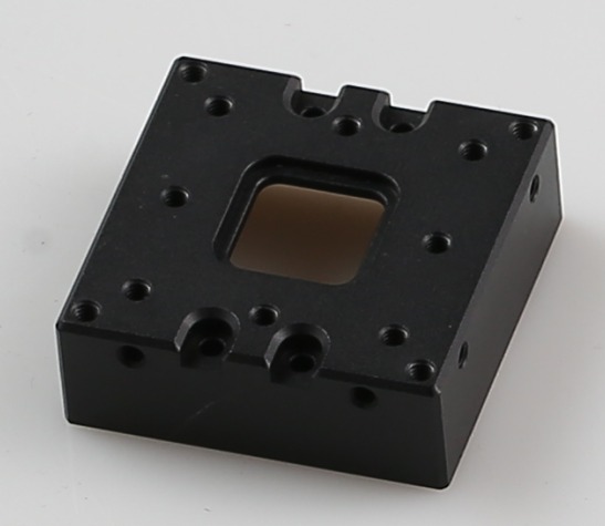
A 3-axis machine cuts everything from one approach direction at a time, so any part with features on more than one face must be re-oriented between operations. Each re-orientation is a re-location of the part in space, and re-location carries error: the fixture seats the part slightly differently, the datum edge is not perfectly square, the work shifts a few microns under the clamp. Features that share a single clamping are located relative to each other with the machine's own accuracy; features separated by a re-fixturing carry that relocation error in addition. So the first question for any dimension is not "can the machine do it" but "are these two features cut in the same setup?"
That is why two drawings can carry identical callouts and yet be completely different jobs. A hole pattern drilled in one clamping holds its spacing to the machine's capability; the same pattern split across two setups inherits the fixture's repeatability. If you learn to sort the drawing into same-setup groups and cross-setup pairs, you already know where the tolerance risk lives before the first quote arrives. And a supplier who sorts the drawing the same way is a supplier whose quote you can trust to meet the drawing rather than to hope about it.
What tolerance can a 3-axis machine honestly hold within one setup?
Within a single rigid setup, with a stable fixture and good practice, a modern 3-axis machining center holds ±0.003 mm on milled features, and features ground after machining reach ±0.002 mm. These are the numbers a competent supplier states for single-setup work, and at production volume the honest proof is process capability of Ppk ≥ 1.67 at the initial study on key characteristics and Cpk ≥ 1.33 on general characteristics. Capability is reported per characteristic: every report names the feature, its tolerance band, the sample size, the sigma method, and the study window, so the number reflects a centered, stable process measured over a run rather than a lucky first part. When you sees ±0.003 mm (milling) / ±0.002 mm (turning) in a quote for features machined in one clamping with a real fixture, that number is believable.
The caveats are the three practical thieves of single-setup tolerance. Thermal growth moves the part and the machine as the day warms. Tool wear changes the effective cutter diameter, which matters most on walls and slots where the size is set by the tool. And fixturing that is not rigid enough lets the part move under the cut, so the tolerance the machine could hold is defeated at the clamp. A good shop controls the first with temperature discipline and compensation, the second by measuring and adjusting mid-run, and the third by designing the fixture for the part. Ask which of these three your part is exposed to, and you are talking to a process engineer.
What happens to tolerance when features cross setups?
When a critical relationship must survive a re-fixture — a bore square to a face cut on the other side, or a row of holes on one face positioned relative to a feature on the opposite face — the tolerance budget has to absorb the relocation error, and the honest supplier says so. The practical rule is to keep the tightest relationships inside one setup wherever the geometry allows: machine the datum faces first, then all features that locate from them in the same clamping. Where a relationship must cross setups, the shop should plan a deliberate re-location — a precision datum, a register feature, or a re-cut reference face — rather than relying on the vise to repeat by itself.
For you, the drawing-level consequence is to question callouts that force the geometry to fight the process. A position tolerance between features on opposite faces tighter than the relocation error budget is a callout the shop can only meet by luck or by a heroic process, and the price will reflect the heroics. The mature move is to discuss the datum scheme with the supplier at the quoting stage: which face carries the datum, which features must be cut in the same setup as that face, and whether the tight relationships can be rearranged onto one clamping. Tolerance is a budget, and the setup plan is where it is spent.
What do the different milling operations leave on the surface?
Surface finish on a 3-axis part is set by the last operation that touched the surface, so reading the drawing surface by surface means asking which operation produces each one. A facing pass with a sharp insert leaves a surface laid by the tool's nose radius and the feed rate; a side wall cut by a long end mill carries the finish of that tool's flute engagement and its deflection; a pocket floor finished with a small stepover shows the scallops of that stepover; and a drilled or reamed bore carries the finish of the cutting edge that formed it. The same material and machine produce very different Ra values depending on the operation, which is why a single finish callout on the whole part is usually meaningless.
As a working map, a normal milled face with a reasonable feed sits around Ra 1.6–3.2 µm; a careful finish pass with light cuts and a small stepover reaches Ra 0.8 µm; and Ra 0.4 µm and finer on a milled part means grinding or polishing rather than a standard milling pass. Your job is to name the Ra on the surfaces that need it and to leave the rest to the natural milling finish, because every surface pulled to a fine finish adds a pass and a price. State the finish with the surface it applies to, and the quote will price the finishes you actually need.
How does tool engagement shape what a milled surface looks like?
The finish a tool leaves is not a property of the machine but of how the tool engaged the material. A finishing pass takes a light radial engagement and a fine feed so the scallop height stays small; a roughing pass takes a heavy cut and leaves a coarse surface regardless of the spindle's quality. On a 3-axis part the achievable finish on a contoured or angled surface is governed by the stepover between passes — tighten the stepover and the surface smooths, at the cost of machine time — and on a wall it is governed by the tool's rigidity and the finish pass parameters. The supplier's finish strategy, stated as a pass plan rather than a promise, is the only reliable predictor of the Ra the part will actually carry.
Watch the two finish hazards specific to milling. The first is chatter: a long thin tool or an aggressive cut makes the tool ring, and the surface comes off washboarded regardless of the programmed finish. The second is tool wear: a dull tool burns or smears the material instead of cutting it, leaving a surface that looks finished and measures wrong. A shop that controls both — by choosing the right tool length and keeping the cutting edge fresh — is a shop whose finish callouts are worth believing. Ask how the shop handles the thin-wall or deep-pocket surfaces on your drawing, and the finish risk on those features becomes visible before the metal does.
When does a milled feature have to leave the 3-axis machine entirely?
Some requirements are beyond what milling can deliver, and the honest quote says so. A bore that must be round and straight beyond the mill's capability moves to a reaming or boring operation on the machine, or to grinding for the tightest sizes. A surface at Ra 0.4 µm or finer is grinding or polishing territory, not a finishing pass. And a feature that the spindle physically cannot reach on a 3-axis — an undercut, a back face, a wall that faces away — needs a different orientation, a different process, or a design change, and the earlier that is said the cheaper it is. The tolerance band ±0.002 mm and the fine finishes are grinding numbers, and a quote that implies milling delivers them on every feature is a quote that has not read its own process.
For you the lesson is to route the drawing honestly: let milling do what milling does well — shape, position and standard finishes across single-setup features — and send the extreme callouts to the operations that own them. A drawing that mixes one grinding-critical feature into an otherwise milled part is not a problem; it is a process plan with two stops. The problem is a drawing that calls every surface to the finest finish and every feature to the tightest band, because that drawing has removed the machinist's freedom to allocate cost where the function actually lives.
How should finish and tolerance be measured on a 3-axis part?
The instruments follow the geometry. Sizes and positions are measured with calibrated gauges and, for the features that carry datum relationships, on a CMM against your datum structure, because a position callout relative to a datum is meaningless if the inspection uses a different reference than the drawing. Surface finish is read with a profilometer tracing the surface in the direction the finish was produced, and a ground surface is measured after grinding, not after a milling pass that was never meant to hold it. The inspection report should name the instrument and the reference for each characteristic, so the numbers can be traced to a method rather than to a hope.
Set the measurement plan when the order is placed, not when the parts arrive. Agree which features carry the tight band and which instrument verifies each, how often the finish is sampled during a run, and what the report will contain — nominal, actual and deviation for every characteristic, finish readings for the surfaces with Ra callouts, and capability data on the key characteristics where your contract demands it. A 3-axis part measured to its own setup plan is a part whose tolerance story has been told in full; one measured by whoever happens to be free is a part whose story will be told later, in a dispute.
How do you put callouts on the drawing that a 3-axis shop can actually hold?
Write the drawing so the setup logic is legible. Choose datum faces that can be machined first and in one setup, locate the critical features from those datums, keep the tightest relationships inside single clamps where geometry allows, and put general tolerances on the features that merely fill space. Name the Ra only on the surfaces that function, and say which surfaces are milled-finish, which need a finish pass, and which must be ground. A drawing written this way does not just describe a part; it describes a feasible process, which is the only kind of drawing that quotes low, machines fast and inspects clean.
Then verify the process with the numbers, not the adjectives. Ask the supplier to state, in writing, the setup count, which features share each clamping, the tolerance per critical feature with its instrument, and the finish per functional surface with its method. If the plan is coherent and the pilot part arrives measuring what the plan promised — the datum relationships inside the budget, the finishes at the Ra you named — the drawing and the shop have agreed on reality. That agreement, not the certificate on the wall, is what makes a 3-axis tolerance real.
What this shop actually runs
Capability evidence should come as specifics, not slogans. Behind this guide is a 6,800 m2 plant in Dongguan, China running 100+ CNC machines with 100+ staff. The machine list by category:
- 5-axis machining centres (10+) - Mazak VARIAXIS I-600 (510/910/510 mm travel, 12,000 rpm, 22 kW, 71.6 N·m, 30-tool BT40) and Mazak INTEGREX I-250H S (B-axis 0.0001°, 24 kW, 124 N·m, 38-tool HSK-A63). Cut on compound-angle parts, single-setup multi-face prismatic work, and aerospace fittings where datum transfer loss is unacceptable.
- 3-axis / 4-axis machining centres (50+) - Brother SPEEDIO S500Z2N / S700Z2N (10,000 rpm, 14/21-tool ATC, 0.7 s tool-to-tool, Z-axis 2.2 G) and Mazak VCE-430A L / VCE-570C L (10,000 rpm, 118 N·m, 24-tool ATC). Cut on prismatic parts, plates, brackets, housings.
- Swiss-type turning centres (10+) - Citizen Cincom A20-3F7 (Φ20 mm, 10,000 rpm), TSUGAMI B0206-III / B0205-III (Φ20 mm, 0.1 µm), STAR SR-32JII / SR-32J Type N (Φ32 mm, 8,000 rpm). Cut on long, slender rotational parts at ±0.002 mm.
- CNC turning centres (20+) - HEADMAN T70M/1250 (720 mm swing, 117 mm bore, 3,000 rpm, BMT75 12-station turret). Cut on shafts, bushings, flanges up to ±0.002 mm.
- Wire EDM (5+) - Sodick AQ535L (550/350/300 mm travel, ±20° taper, 800 kg workpiece). Cut on hardened tool steel, internal splines, sharp internal corners that milling cannot reach.
- Inspection: Hexagon CMM + 20+ gauges - Hexagon CMM for coordinate measurement, plus vision system, profilometer, hardness tester, coating thickness gauge, XRF for material verification. The 10:1 rule (gauge 10x more accurate than the band) is applied to every feature.
- Machine highlights - VARIAXIS I-600: one-setup multi-face 5-axis + MAZA-CHECK auto-calibration; INTEGREX I-250H S: DONE-IN-ONE mill-turn, B-axis 0.0001° + Ai thermal shield; SPEEDIO S500Z2N / S700Z2N: Z-axis 2.2 G + 0.7 s ATC; Swiss-type: guide-bush switchable + 0.1 µm resolution.
Tolerance: ±0.003 mm CNC milling / ±0.002 mm CNC turning / ±0.002 mm grinding and wire EDM. Capability: Ppk >= 1.67 initial on key characteristics, Cpk >= 1.33 ongoing.
Certificates: ISO 9001:2015 (116024/A/0001/UK/En), IATF 16949:2016 (131941/A/0001/SM/En, with design clause 8.3 excluded, stated openly) and ISO 14001:2015 (116024/B/0001/UK/En), issued to Dongguan Zhuohang Ltd, registration 91441900MA4UWT6X39, founded 2005.
Where we ship: Austria, Belgium, the Czech Republic, Denmark, France, Germany, Greece, Hungary, Ireland, Italy, the Netherlands, Spain, Sweden and the United Kingdom in Europe; Brazil, Canada, Mexico and the United States in the Americas; China, Israel, Japan, Singapore and Sri Lanka in Asia; Australia and New Zealand in Oceania; and South Africa in Africa — plus other countries and regions worldwide, shipped from our base in Dongguan, China.
Contact: Felipe Iglesias, [email protected], +86 13126536955.
Setting tolerances on a prismatic part and want the setup logic confirmed?
Email the STEP model and toleranced drawing to [email protected] or call +86 13126536955. You get the setup count, the datum strategy, and the tolerance and finish per feature with the instrument that verifies it. See the quality page for the inspection framework and the services page for the operations behind the numbers.
Frequently Asked Questions
Why does setup count decide what tolerance a 3-axis part can hold?
Features cut in one clamping are located with the machine's accuracy; features separated by a re-fixture carry the relocation error of the new setup. Sorting the drawing into same-setup groups shows where the tolerance risk lives.
What tolerance can a 3-axis machine hold in one setup?
In short, ±0.003 mm on milled features and ±0.002 mm on precision ground surfaces, with Ppk ≥ 1.67 at the initial study on key characteristics and Cpk ≥ 1.33 on general characteristics. Capability is reported per characteristic: every report names the feature, its tolerance band, the sample size, the sigma method, and the study window at volume.
What Ra should I expect from standard 3-axis milling?
Around Ra 1.6–3.2 µm from normal milling, Ra 0.8 µm from a careful finish pass with light cuts, and Ra 0.4 µm and finer only from grinding or polishing. Name the Ra per surface or the quote will guess.
Can a finish pass really improve the tolerance too?
Yes — the same light finishing pass that smooths the surface also removes the deflection and wear errors of the roughing cut, which is why features that carry both tight tolerance and fine finish are finished in one careful pass.
When does a milled feature need grinding instead?
When it needs ±0.002 mm or a finish at Ra 0.4 µm or finer, or when the material is too hard for milling to hold the edge. Route those callouts to the operation that owns them instead of asking milling to fake it.
How should finish be measured on a milled surface?
With a profilometer tracing the surface in the direction the finish was produced, and ground surfaces measured after grinding. The report should name the instrument so the Ra number can be traced to a method.
What makes a tolerance real on a 3-axis part?
In short, A drawing whose datum scheme matches a feasible setup plan, a supplier who states the setup count and the per-feature instruments, and a first article that measures what the plan promised. That agreement is what the certificate on the wall cannot replace.
Standards referenced on this page
- ASTM A582/A582M-12 — Standard Specification for Free-Machining Stainless Steel Bars
- ASTM B211/B211M-19 — Standard Specification for Aluminum-Alloy Rolled or Cold Finished Bar, Rod, and Wire
- ISO 9001 — Quality management systems — Requirements