

1. What 3-axis CNC milling is
3-axis milling cuts a stationary workpiece with a spinning tool that moves along X (left–right), Y (front–back) and Z (up–down). The tool approaches the top and sides of the part from fixed directions; anything on the bottom or at a compound angle needs the part to be re-fixtured. That is the defining limit of 3-axis: three straight-line directions, no tilting of the tool or part during the cut.
Milling is the workhorse for prismatic parts — brackets, plates, housings, fixtures, manifolds — anything blocky or plate-shaped with features on several faces. Unlike a router (built for soft materials at high speed), a mill is rigid enough to cut steel and titanium, which is why it is the default for metal components.
Most 3-axis work is "2.5D" rather than full 3D: the tool travels in X/Y to position and plunges in Z, so the part is built from flat-bottomed pockets, steps, holes and profiles rather than sculpted curves. That is exactly what the majority of functional components need — a bracket does not require a 5-axis contour, it requires accurate holes and flats on three faces — and it is also the cheapest way to buy the part, because you are not paying for the extra rotary axes, the longer setup, or the programmer time a multi-axis job demands.
The honest boundary matters when you brief a shop. A 3-axis mill reaches the top face and the four side faces of a cube-shaped blank in up to five setups, but it cannot reach the bottom face without flipping, and it cannot cut a feature that sits at a compound angle to the axes without tilting the tool or the part. Undercuts, intersecting holes at angles, and wrapped surfaces are the classic signals that the geometry wants 4-axis or 5-axis rather than 3. Calling this out early saves a redesign late.
2. How it works in practice
- CAD → CAM → G-code. Your model becomes toolpaths; the shop selects tools, depths and order.
- Workholding. Vises, soft jaws, custom fixtures or clamps hold the part. More faces = more setups = more cost and alignment risk.
- Tooling. End mills (square, ball-nose, corner-radius), drills, reamers and taps. Tool choice drives finish and accuracy.
- Speeds, feeds, coolant. Aluminum can be cut fast; titanium needs slower, rigid setups and good cooling. This is where experience shows.
What this workflow means for you is that the number of setups is usually the biggest single cost and accuracy lever. Every time the part is unclamped and re-fixtured, the shop pays for a fresh datum and accepts a small registration risk between faces. A part finished in one or two setups is cheaper and more accurate than the same part designed so that three faces each need a flip. When you read a quote, ask how many setups it took, that often explains the number better than the machine-hour rate does.
A practical note on datums: the shop picks one face or edge as the primary datum and references everything else to it. If your drawing calls out functional datums, they should match the setups that are actually possible; a datum on a face that cannot be fixtured first creates a measurement loop no machine can close. Stating datums on the drawing, rather than leaving them implicit, is one of the cheapest accuracy improvements available.
3. Equipment, spindles and tool holders
The machine at the centre of the process is a machining center: a rigid base, a table that moves in X and Y, and a spindle head that moves in Z. For 3-axis work the default is the vertical machining center (VMC), where the spindle points down and the table carries the part. Gravity holds the blank on the table and the operator loads from the front, which is why VMCs dominate prototype and low-volume metal work. Horizontal machining centers exist for higher-volume runs where a tombstone fixture presents parts on several sides at once, but most buyers will be quoted a VMC.
Three specifications decide what the machine does for you. Spindle speed and power set removal rate and finish — a 10,000–15,000 rpm direct-drive spindle covers most aluminium and steel, while tougher alloys benefit from torque at lower speed. Travel (the X/Y/Z envelope) sets the largest part that fits; a 500×400×300 mm bed handles most bracket- and plate-class work, and larger beds exist for big plates. Positioning repeatability of the scales and ballscrews is what lets a capable machine hold tight bands shift after shift, not just on a good day.
Cutting tools seat in a spindle taper — BT (common on Asian- and Japanese-built machines) or CAT (the inch US standard, sized 30/40/50). The holder must match the spindle; beyond that, holder quality matters more than the brand. A balanced shrink-fit or high-precision collet holder runs truer than a worn kickback holder, and true-running tooling is what preserves tolerance and finish across a long run.
Workholding is where buyers most often underestimate cost. A machine vise suits rectangular blanks, but soft jaws or a dedicated fixture hold a thin or oddly shaped part without distorting it, and let one setup cover features that would otherwise need a flip. Ask how the part will be held, not just what machine will cut it.
4. Materials and tolerances
| Material | Typical use | Buyer notes |
|---|---|---|
| Aluminum (6061, 7075) | Frames, enclosures, heatsinks | Easy to machine, excellent for prototypes and production |
| Stainless (304, 316) | Medical, food, marine | Work-hardens; needs rigid setups |
| Steel (1018, 4140) | Structural, jigs | Predictable, strong |
| Titanium | Aerospace, medical | Low thermal conductivity; control heat |
| Brass / copper | Connectors, EMI parts | Free-cutting, but soft |
| PEEK / Delrin (POM) | Insulators, wear parts | Engineering plastics; chip control matters |
A realistic, repeatable tolerance on milled features is ±0.003 mm (±0.0002 in) for critical dimensions on capable equipment; non-critical features can be looser to save cost. Over-tolerancing everything is the most common way to inflate a quote. For context, large Machining platforms quote a standard metal tolerance around ±0.005 in (±0.127 mm) referenced to ISO 2768, with an as-machined surface of Ra 125 µin (3.2 µm) as the starting point. Our ±0.003 mm milling band is tighter, but it should be read honestly: the achievable number depends on feature size, material and volume, and a ±0.003 mm call on a two-metre plate is a different proposition from the same call on a 20 mm boss. Tight tolerances belong on the dimensions that are functional, not on the drawing as a default.
5. Surface finish and what "as-milled" means
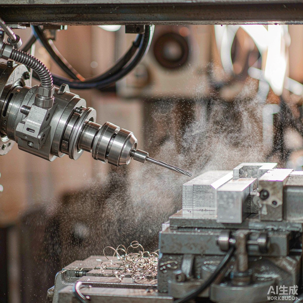
Straight off the machine, a milled face typically shows Ra 3.2 µm (125 µin) — visible tool marks, perfectly serviceable for most structural and mounting faces, but not cosmetic. A finer finish needs a dedicated finishing pass with a smaller stepover, which costs cycle time, so it should be called out only where it matters: sealing faces, sliding surfaces, or appearance parts. What "as-milled" does not mean is "any finish the shop felt like" — you should name the Ra where it is important and leave the rest open, exactly as with tolerances.
Secondary finishes are a separate decision. Bead blasting, anodising (aluminium), passivation (stainless), powder coating and plating each add thickness and lead time, and each changes fit on threaded or press-fit features unless the allowance is stated. A coating applied after final inspection changes the dimension it covers, so the drawing must say which features are coated and by how much.
6. DFM checklist for milled parts
Design for manufacture is where most quote surprises are born. The rules below are the ones that move cost and yield the most:
- Wall thickness. Keep walls at or above roughly 0.8–1.0 mm on metal; thinner walls chatter, distort as residual stress is released, and are hard to hold to size. If a thin wall is unavoidable, expect a stress-relief step between roughing and finishing.
- Minimum feature size. Slots, pockets and bosses smaller than the smallest tool that can reach them cannot be cut cleanly. A 2 mm end mill is a practical lower bound for deep features; smaller needs specialist tooling and more time.
- Internal corners need radii. A square internal corner forces the tool to a zero-radius point and leaves a fillet anyway. Designing a corner radius that matches a real cutter (say 1–3 mm) removes a finishing operation and improves accuracy.
- Datum strategy. Pick primary, secondary and tertiary datums that the shop can actually fixture, and reference tight features to them. A datum on an unmachinable face creates a loop that cannot be closed.
- Standardise holes and threads. Using standard drills and off-the-shelf taps reduces special tooling and speeds the job.
- Design for setups. Features reachable in one or two setups cost far less than the same geometry scattered across five faces. Group features by accessible face when you can.
7. Cost drivers
A 3-axis milling quote is not one number but a sum of identifiable drivers. Knowing them lets you challenge a quote or redesign for cost:
- Setup time. Fixturing, probing and the first-article check dominate low-volume work. One setup beats three.
- Cycle time. Driven by material (titanium is slow, aluminium fast), feature depth, corner radii and finish. Long tools in deep pockets are the enemy of speed.
- Material. Stock cost and machinability both count; exotic alloys cost more per kilo and per hour.
- Tolerance and finish. Tight bands and fine Ra add passes, measurement and scrap risk.
- Volume. A hundred parts amortises setup; ten do not. Below a threshold, setup rules the price.
- Post-processing. Anodise, passivate, heat treat, coat and inspect — each adds a line item.
- Tariffs and freight. For cross-border sourcing, metal parts can carry layered US duties: MFN plus Section 301 List 1–3 (25%) or List 4A (7.5%) plus Section 232 where it applies. These are real cost lines you should model, not an afterthought.
8. Comparison: 3-axis vs other processes
Choosing 3-axis is a decision, not a default. The table frames where it wins and where another process is cheaper or simply capable:
| Process | Best for | Limit vs 3-axis | When to choose it |
|---|---|---|---|
| 3-axis milling | Prismatic parts, multi-face features, low–mid volume | Cannot reach undercuts or compound angles in one setup | The default for brackets, plates, housings |
| 4-axis milling | Parts needing one rotary index (holes around a cylinder) | Still no full compound-angle reach | Rotationally featured parts, indexable drilling |
| 5-axis milling | Compound-angle features, impellers, moulds | Higher machine-hour and programming cost | When the geometry genuinely needs tilting |
| Turning (CNC lathe) | Round, rotationally symmetric parts | Poor for prismatic, flat features | Shafts, bushings, threaded round parts |
| Casting / forging + machining | High-volume complex shapes | Hard tooling cost, lead time, minimum volume | When volume justifies hard tooling |
The common pattern is a part that is mostly prismatic but has one round feature: it is milled, then the round feature is turned, or vice versa. Specifying the dominant process and adding the other as a secondary operation is usually cheaper than forcing everything onto one machine.
9. RFQ checklist
- STEP/IGES model (not a PDF or screenshot).
- Material and grade; note heat treatment.
- Quantities and annual volume.
- Tolerances only where functional.
- Surface finish (e.g., visible-face requirement, anodize, bead blast).
- Threads, bores, and any post-processing.
A complete RFQ does more than speed a quote — it pre-empts the questions that otherwise arrive as delays. Where you supply a STEP model, a named grade, functional tolerances only, and the finish and volume, the shop can quote from the file instead of from assumptions, and the first-article part matches the expectation. The single most valuable line on an RFQ is often "tolerance only where functional," because it stops a supplier from pricing every dimension to ±0.003 mm.
10. How to qualify a CNC shop
Before sending production work, you should verify a shop on points that actually predict a good outcome:
- Certificates with checkable numbers. Ask for ISO 9001:2015 (116024/A/0001/UK/En), IATF 16949:2016 (131941/A/0001/SM/En) and ISO 14001:2015 (116024/B/0001/UK/En). Note the IATF certificate excludes clause 8.3 (product design) — normal for a build-to-print shop, and worth stating so there is no confusion about who owns the design.
- A real plant, not a trading desk. The legal entity should be a manufacturer — for example Dongguan Zhuohang Ltd, Tax ID 91441900MA4UWT6X39, a 6,800 m² facility in Dongguan Hengli with 100+ CNC machines. A trading licence shows a trading scope and an office, not a plant.
- A manufacturability review before quote. A shop that flags risky features up front is protecting your yield, not padding its price.
- Capability stated with method. A tolerance claim should come with the process and the measuring method, not as a bare number.
- Spare capacity. Shops with depth across 3/4/5-axis and turning can move work internally when one machine is down, which protects your lead time.
We are transparent about what we do not hold: there is no AS9100, no NADCAP and no ISO 13485 on site. For aerospace or medical work that needs third-party ultrasonic testing (ASTM B594) or regulated quality systems, that work is routed to an external accredited laboratory, and we will say so before you commit rather than after.
11. Common mistakes buyers make
- Tolerancing every dimension. Tight specs on non-critical features raise scrap and price.
- Designing for one setup when geometry needs three. Undercuts and back-face features force flips; design with setups in mind.
- Vague material calls. "Aluminum" is not a spec; "6061-T6" is.
- Skipping finish requirements. Leaving finish open leads to inconsistent results across reorders.
Most of these mistakes share one root cause: the drawing was written for the ideal part rather than for the process that will make it. A tolerance on every dimension, a feature on a hidden face, a vague material call, and an open finish spec each push cost or risk upward for no functional gain. The fix is to design and specify for the process, which is what the rest of this guide is for.
12. Industry applications
3-axis milling shows up wherever a flat-, block- or plate-shaped metal part has to be accurate and repeatable:
- Automotive and EV. Brackets, housings, busbars and fixture details — the IATF 16949 scope covers production parts for this sector.
- Electronics and enclosures. Aluminium frames, heatsinks and connector bodies where flatness and hole patterns matter.
- Industrial equipment. Jigs, fixtures, machine guards and replacement parts in steel and stainless.
- Medical and food (non-implant). 304/316L fixtures, trays and tooling — note we are not ISO 13485-certified, so regulated implant work is outside our scope.
- Robotics and automation. Mounting plates and arms where multiple faces carry features.
13. How a capable shop approaches milling
Competence shows in specifics: they own rigid machines (Mazak, Brother, Tsugami and similar) with the spindle and control to hold tight tolerances repeatably; they run documented quality so reorders match first articles; and they review your file for manufacturability before quoting rather than after a scrap run. At Zhuohang Precision Machining Factory, 3-axis milling sits among 100+ CNC machines in a 6,800 m² facility in Dongguan Hengli, with milled-feature tolerances to ±0.003 mm (milling) / ±0.002 mm (turning), supported by in-house turning, wire EDM and grinding so a mixed-geometry part stays under one quality system. The certificates, the IATF 16949 clause 8.3 exclusion, the capability thresholds and the aerospace/medical gaps are set out in the shop-qualification section above; the practical point is that all of it is verifiable and stated before you commit, not discovered at first article. Reach the team via Felipe Iglesias at [email protected] or +86 13126536955.
What this shop actually runs
Capability evidence should come as specifics, not slogans. Behind this guide is a 6,800 m2 plant in Dongguan, China running 100+ CNC machines with 100+ staff. The machine list by category:
- 5-axis machining centres (10+) - Mazak VARIAXIS I-600 (510/910/510 mm travel, 12,000 rpm, 22 kW, 71.6 N·m, 30-tool BT40) and Mazak INTEGREX I-250H S (B-axis 0.0001°, 24 kW, 124 N·m, 38-tool HSK-A63). Cut on compound-angle parts, single-setup multi-face prismatic work, and aerospace fittings where datum transfer loss is unacceptable.
- 3-axis / 4-axis machining centres (50+) - Brother SPEEDIO S500Z2N / S700Z2N (10,000 rpm, 14/21-tool ATC, 0.7 s tool-to-tool, Z-axis 2.2 G) and Mazak VCE-430A L / VCE-570C L (10,000 rpm, 118 N·m, 24-tool ATC). Cut on prismatic parts, plates, brackets, housings.
- Swiss-type turning centres (10+) - Citizen Cincom A20-3F7 (Φ20 mm, 10,000 rpm), TSUGAMI B0206-III / B0205-III (Φ20 mm, 0.1 µm), STAR SR-32JII / SR-32J Type N (Φ32 mm, 8,000 rpm). Cut on long, slender rotational parts at ±0.002 mm.
- CNC turning centres (20+) - HEADMAN T70M/1250 (720 mm swing, 117 mm bore, 3,000 rpm, BMT75 12-station turret). Cut on shafts, bushings, flanges up to ±0.002 mm.
- Wire EDM (5+) - Sodick AQ535L (550/350/300 mm travel, ±20° taper, 800 kg workpiece). Cut on hardened tool steel, internal splines, sharp internal corners that milling cannot reach.
- Inspection: Hexagon CMM + 20+ gauges - Hexagon CMM for coordinate measurement, plus vision system, profilometer, hardness tester, coating thickness gauge, XRF for material verification. The 10:1 rule (gauge 10x more accurate than the band) is applied to every feature.
- Machine highlights - VARIAXIS I-600: one-setup multi-face 5-axis + MAZA-CHECK auto-calibration; INTEGREX I-250H S: DONE-IN-ONE mill-turn, B-axis 0.0001° + Ai thermal shield; SPEEDIO S500Z2N / S700Z2N: Z-axis 2.2 G + 0.7 s ATC; Swiss-type: guide-bush switchable + 0.1 µm resolution.
Tolerance: ±0.003 mm CNC milling / ±0.002 mm CNC turning / ±0.002 mm grinding and wire EDM. Capability: Ppk >= 1.67 initial on key characteristics, Cpk >= 1.33 ongoing.
Certificates: ISO 9001:2015 (116024/A/0001/UK/En), IATF 16949:2016 (131941/A/0001/SM/En, with design clause 8.3 excluded, stated openly) and ISO 14001:2015 (116024/B/0001/UK/En), issued to Dongguan Zhuohang Ltd, registration 91441900MA4UWT6X39, founded 2005.
Where we ship: Austria, Belgium, the Czech Republic, Denmark, France, Germany, Greece, Hungary, Ireland, Italy, the Netherlands, Spain, Sweden and the United Kingdom in Europe; Brazil, Canada, Mexico and the United States in the Americas; China, Israel, Japan, Singapore and Sri Lanka in Asia; Australia and New Zealand in Oceania; and South Africa in Africa — plus other countries and regions worldwide, shipped from our base in Dongguan, China.
Contact: Felipe Iglesias, [email protected], +86 13126536955.
Next step: Send your model for a manufacturability review. See our resources page for RFQ templates.
Frequently Asked Questions
What tolerance can 3-axis CNC milling hold?
On well-maintained equipment with sensible tooling, milled features commonly hold ±0.003 mm (±0.0002 in) for critical dimensions. Looser bands are fine for non-critical features and keep cost down.
What materials can be 3-axis milled?
Most metals — aluminum, steel, stainless, titanium, brass, copper, Inconel — plus engineering plastics such as PEEK and Delrin/POM. Material choice drives tooling, coolant and cycle time.
When should I choose milling over turning?
Milling suits prismatic, blocky or plate-shaped parts with features on multiple faces. Turning suits round, rotationally symmetric parts. Many real parts use both in sequence.
How do I write an RFQ for milled parts?
Send a STEP/IGES model, material and grade, quantities, tolerances only where functional, surface-finish needs, and any threading or post-processing. The more precise the brief, the tighter the quote.
Standards referenced on this page
- ASTM B211/B211M-19 — Standard Specification for Aluminum-Alloy Rolled or Cold Finished Bar, Rod, and Wire
- ASTM A276/A276M-17 — Standard Specification for Stainless Steel Bars and Shapes
- ISO 9001 — Quality management systems — Requirements